Tutorials
FPGA Toolkit
The process of building a partially reconfigurable design is broken into two portions. First the static design must be generated. This design contains all the inputs and outputs to the external world in addition to the portion of the design that will not change between modules. For the purposes of this tutorial the counter example will be evaluated on the Xilinx XUPV5.
Static Design
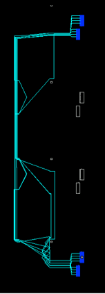
Other than the reset logic, this design does not contain any logic outside of the reconfigurable modules. First bus macros must be declared in the design. For the counter example there are 8 nets that traverse the boundary from the static to the reconfigurable region. The picture to the left shows an FPGA editor screenshot of the hard macro bus macro that is generated. The portion where the nets line up is the boundary between the static region above and the reconfigurable region below. The component declaration and instantiation is below to show how these bus macros are inserted into the VHDL.
-
1. component busmacro_xc5v_async_vert_input_0 port(
-
2. input0 : in std_logic;
-
3. input1 : in std_logic;
-
4. input2 : in std_logic;
-
5. input3 : in std_logic;
-
6. input4 : in std_logic;
-
7. input5 : in std_logic;
-
8. input6 : in std_logic;
-
9. input7 : in std_logic;
-
10. output0 : out std_logic;
-
11. output1 : out std_logic;
-
12. output2 : out std_logic;
-
13. output3 : out std_logic;
-
14. output4 : out std_logic;
-
15. output5 : out std_logic;
-
16. output6 : out std_logic;
-
17. output7 : out std_logic);
-
18. end component;
-
19. attribute box_type of busmacro_xc5v_async_vert_input_0: component is "black_box";
-
20. attribute lock_pins of busmacro_xc5v_async_vert_input_0: component is "true";
-
21. -- Output bus-macro
-
22. busmacro_xc5v_async_vert_output_0_0 : busmacro_xc5v_async_vert_output_0 port map(
-
23. passthrough_wires(0), passthrough_wires(1), passthrough_wires(2), passthrough_wires(3), passthrough_wires(4), passthrough_wires(5), passthrough_wires(6), passthrough_wires(7),
-
24. data_reg_o(0), data_reg_o(1), data_reg_o(2), data_reg_o(3), data_reg_o(4), data_reg_o(5), data_reg_o(6), data_reg_o(7));
-
1.# PlanAhead generated physical constraints
-
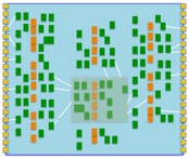
2.AREA_GROUP "counter" RANGE=SLICE_X10Y80:SLICE_X27Y99;
The reconfigurable region is defined by the UCF file above. This UCF file will be used throughout the entire OpenPR process to control the placement of both the static and reconfigurable regions.
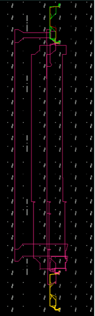
The route_passthroughs.scr file must also be modified to reflect the passthrough nets in the PR region. These nets are reflected in pink in the diagram to the right. They must be placed in the design to complete the connections between the input and output bus macros to prevent them from being ripped out by MAP for being dangling instances. The modifications should simply reflect the names for the passthrough nets as they would appear in the XDL after synthesis. For example in the VHDL in this design the pass through nets are defined as:
-
1.setattr main edit-mode Read-Write
-
2.select net passthrough_wires<0>
-
3.select net passthrough_wires<1>
-
4.select net passthrough_wires<2>
-
5.select net passthrough_wires<3>
-
6.select net passthrough_wires<4>
-
7.select net passthrough_wires<5>
-
8.select net passthrough_wires<6>
-
9.select net passthrough_wires<7>
-
10.autoroute
-
11.save
-
12.exit
signal passthrough_wires : std_logic_vector(7 downto 0);
After this design passes through Synthesis, Translate, and Map, the nets become named as below with the bus being broken into individual nets with the <#> suffix.
Finally the XML project file for the sandbox must be be modified to reflect the proper sandbox settings. First the name of the reconfigurable region must be identified to prevent the placement of the static design. The name and size of the bus macro primitive needs to be placed in the XML project file. The passthroughNet and clock net also needs to be identified.
-
1. <dynamicAGName>counter</dynamicAGName>
-
2. <busMacroPrefix>busmacro_xc5v_async_vert</busMacroPrefix>
-
3. <busMacroNames class_id="1" tracking_level="0" version="0">
-
4. <count>0</count>
-
5. <item_version>0</item_version>
-
6. </busMacroNames>
-
7. <passThroughNetName>passthrough_wires</passThroughNetName>
-
8. <clkNetNames class_id="1" tracking_level="0" version="0">
-
9. <count>1</count>
-
10. <item_version>0</item_version>
-
11. <item>clk_BUFGP</item>
-
12. </clkNetNames>
-
13. <busWidth>8</busWidth>
-
14. <deviceName>xc5vlx110t-ff1136-1</deviceName>
Partial Modules
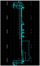
Partial modules are the partially reconfigurable regions in Open PR. For the example of the counter they can change the way that the counter performs from an increment counter to a decrement counter. For the purposes of this tutorial the decremental partial module will be evaluated. There are two main VHDL files, the top level module, and the partial module, that are utilized in this design. The first file shown below is the same sandbox,vhd file from the static module. This file is modified to remove the passthrough signals and add the reconfigurable module
-
1. -- Reconfigurable module instantiation
-
2. decrement : prm port map(clk, module_in,module_out);
-
3. -- Output bus-macro
The partial module must the be defined as in the following VHDL file
-
1.entity prm is port(
-
2. clk : in std_logic;
-
3. data_in : in std_logic_vector(7 downto 0);
-
4. data_out : out std_logic_vector(7 downto 0));
-
5.end prm;
-
6.
-
7.architecture prm of prm is begin
-
8. process(clk) begin
-
9. if(clk = '1' and clk'event) then
-
10. data_out <= data_in - 1;
-
11. end if;
-
12. end process;
-
13.
-
14.end architecture prm;
Again as in the static region, the scripts must be modified to reflect the input and output nets. Both the route_passthroughs.scr and the unroute_passthroughs,scr must be modified to reflect the connection nets out to the bus-macros. An example for the route_passthroughs.scr is shown below. Notice again how the bus is transformed into individual nets by adding a <#> as a suffix.
In addition, the project XML file must be modified to reflect the partial design. These modifications include setting the partial flag to 1, and setting the input and output pass through nets as passThroughNetName and passThroughNetName2 respectively.
-
1.setattr main edit-mode Read-Write
-
2.select net data_reg_i<0>
-
3.select net data_reg_o<0>
-
4.select net data_reg_i<1>
-
5.select net data_reg_o<1>
-
6.select net data_reg_i<2>
-
7.select net data_reg_o<2>
-
8.select net data_reg_i<3>
-
9.select net data_reg_o<3>
-
10.select net data_reg_i<4>
-
11.select net data_reg_o<4>
-
12.select net data_reg_i<5>
-
13.select net data_reg_o<5>
-
14.select net data_reg_i<6>
-
15.select net data_reg_o<6>
-
16.select net data_reg_i<7>
-
17.select net data_reg_o<7>
-
18.autoroute
-
19.save
-
20.exit
-
1. <isPartial>1</isPartial>
-
2. <passThroughNetName>data_reg_i</passThroughNetName>
-
3. <passThroughNet2>data_reg_o</passThroughNet2>
Both the partial and the sandbox bitstreams will need to be compiled by first sourcing the Xilinx Tools. Then in the sandbox folder type:
make
To compile the partial bitstreams enter the appropriate partial folder and type:
make partial