Screenshots
FPGA Toolkit

OpenPR in action...
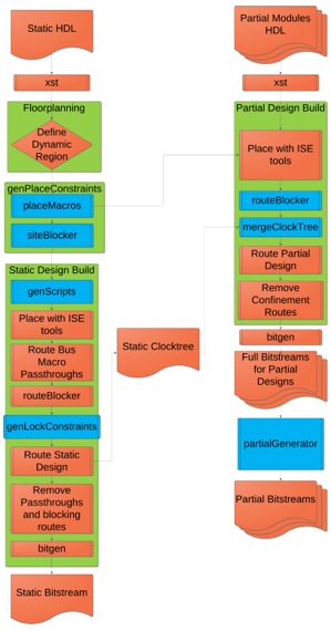


The process that OpenPR utilizes to generate both the static and partial bitstreams is outlined to the left. This process will be described in detail throughout this page.
Static Flow
Floorplanning
The first task of FloorPlanning is accomplished by hand, utilizing PlanAhead as a guide. This will help approximate the appropriate size for the PR module.
PlaceMacros
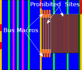
The bus macros are then placed in the design. It is required that the number of inputs and output into the design are equivalent, The bus macros are placed on the iteratively from the North West and South West corners of the design and iterate toward the East
SiteBlocker
The site blocker iterates through all sites in the PR region and adds them to the UCF file as a prohibit constraint.
INST "busmacro_xc5v_async_vert_input_0_0" LOC="SLICE_X11Y99";
INST "busmacro_xc5v_async_vert_output_0_0" LOC="SLICE_X11Y80";
CONFIG PROHIBIT="PMVBRAM_X0Y4";
CONFIG PROHIBIT="RAMB36_X0Y16:RAMB36_X0Y20";
CONFIG PROHIBIT="GLOBALSIG_X6Y4";
CONFIG PROHIBIT="TIEOFF_X6Y78:TIEOFF_X6Y101";
...
BusMacro HardMacro
Route Bus Macro Passthroughs
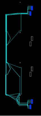
The input and output bus macros must be connected to each other through passthrough routes. If these are not completed the placer will rip out the bus macros. As seen in the figure to the right the pink wires are the routes that connect the bus macros, with the green being the input into the partial module bus macro set, and the yellow is the output from the partial module bus marco set.

RouteBlocker
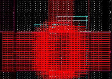
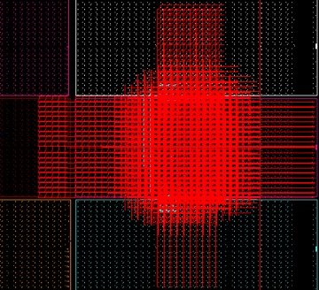
An anti-core must be utilized to keep all routing out of the partial region. This anti-core uses all routing wires that have either a source or destination within the partial region. This is why the are long lines that are leaving the area of the partial region
Route Static Design
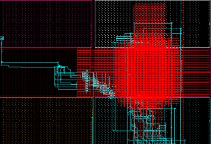
With the route blocker anti-core in place the static design is routed routed. Because PAR is a on-constrainable router, FPGA Editor’s router is being utilized to route the static design. The route design is outlined in blue, while the route blocker is in red. Note that on the perimeter of the route blocker there are static routes, as these do not directly enter the partial region.
Remove the routeblocker
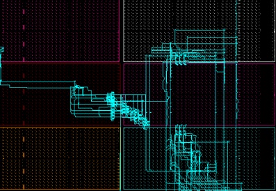
The route blocker is removed an a pristine sandbox can be seen in the diagram to the right.
Partial Designs
For the partial design generation, the process is similar to the static design, except that the placement is constrained to the partial region, and the routeblocker is on the boundary of the partial region. As can be seen in the diagram to the right, the area in the center of the partial region still has many available routing resources. Because of the richness of the routing resources on the FPGA, the resources that start and end within the partial region are allowed. This is necessary as a partial bitstream is generated that contains only the frames that are necessary for the partial module.